Abstract: This paper introduces the economical large-scale AnSH PLC and the economical compact FX2N PLC and its corresponding function module and FR-540 frequency converter, and adopts the fieldbus CC-1 with high transmission rate and good reliability. Link, the structure of a set of real-time strong, reliable and accurate real-time distributed remote simulation system. The development of the system provides a practical and semi-physical simulation platform for the development of marine vessels, which saves a lot of test and test funds, reduces the material and manpower required for the test. At the same time, it can also carry out marine energy development The simulation test, to fill the gaps in the industry.
Key words: PLC semi-physical simulation CC-Link
1. design background
The swing attitude of the ship in the ocean, the hull of the wind and waves on the stability of the ship’s navigation, safety is of great significance. Hull in the ocean in different sports posture: horizontal, vertical, up and down on behalf of different sea level, the ship’s airworthiness level is an important indicator of marine ships. Therefore, in the design of ships, especially ocean-going ships, marine ship design, must be scientifically calculated its hull’s anti-storm level. But the calculation is only theoretical value, must be repeated after several sea storm test to be amended. This test is not only time-consuming, laborious, but also a lot of waste of financial resources. Some units in order to reduce expenses, the sea storm test to the lowest number, not only affects the integrity of the test data, and some data is not necessarily complete. In order to avoid this phenomenon, so that ocean and ocean ship design more scientific, time-saving, effort, provincial funding, we use the R & D automation of large practical PLC AnSH and the economy compact FX2NPLC, FR-E540 inverter, And the use of CC-Link field bus, developed a 50 meters long, 30 meters wide, 6 meters deep pond wave system, can simulate the real-time sea conditions of the storm, to achieve the ship design of the five-in-kind simulation system platform, not only can provide The ship design unit and the ship certification unit for real-time simulation of semi-physical test for the ship design to provide close to the actual sea conditions of the test site data, but also for the marine development unit for wave energy generation device development research. This kind of semi-physical distributed simulation platform system in foreign countries have been formed in the 1990s, ship design units in China is currently under trial work.
System composition and design
2.1 system components
In order to simulate the wind and waves, water flow, wave course and wave height in real time, the system has the following subsystems
1) wave-making system: the pool is equipped with three sets of dual-push plate high-power wave machine and low-power wave machine, large, small wave machine can produce a combination of different longitudinal wave propagation, the maximum wave up 0.3 meters, by the computer program control, can produce the model test required by the regular or irregular waves.
2) flow system: the pool is equipped with a set of high-pressure water flow system, in the pool wall on both sides of the uniform spray pipe, the pump from the thick pipe after the pressurized water spray from the spray pipe, caused in the pool Uniform water flow. The system can produce longitudinal and lateral flow, the maximum flow rate of 0.1 m / s. In addition, a local flow system is configured to accommodate high-speed water flow and the need for different flow tests.
3) Wind system: configure a set of mobile blower wind system. The maximum wind speed of up to 5 m / s, through the computer control system can simulate the spectrum.
4) trailer system: in the tow test can be carried out waves, waves and waves of the tow test, but also on the x, y direction of the adjustment of the towing drag test.
5) pool filtration system: the pool is equipped with mechanical filtration system.
6) wave elimination system: in the other side of the wave machine with a certain degree of slope of the grid-type smoke wave, so as to absorb the wave to prevent the generation of reflected waves.
2.2 system design
In order to achieve the above functions, the system uses hierarchical, sub-unit concept, the system to achieve true distributed control. Among them, the wave-making system, the flow sub-system and the wind sub-system, respectively, can be controlled by two PLC, the sea waves are waves, waves, ripple waves, in order to truly simulate the characteristics of sea conditions, taller waves Controlled by AnS PLC, small waves, ripple waves controlled by FX2N PLC. The faction system is similar. Only in this way can we simulate the tide of the two big tides in the sea. The process of the tide is: the output frequency of the FR-E540 frequency converter is controlled by the control signal of 0 ~ 10V output from the analog output function module of the PLC. The inverter real-time controls the speed of the three-phase asynchronous motor, To combat the water surface, the motor speed is different, resulting in two wave between the wave and the peak of the different, so that the three-phase asynchronous motor with different speeds of different wave head, wave, peak corresponding, therefore, two three Phase asynchronous motor combination of different speed can be real-time reproduction simulation of different sea conditions. The flowmaking system is also controlled by the AnSH PLC and the FX2N PLC to control the respective power pumps to form different water flows. The wind-making system is controlled by AnSH PLC to control high-power fan.
In order to improve the reliability, the control system is also designed manual standby speed control system to ensure that the computer failure does not affect the wave. When the computer fails, the switching device without manual intervention, switch to the manual standby speed control system, the operator can adjust the inverter speed through the potentiometer to maintain the normal wave-making process. Three system configurations consisting of AnSH PLC, FX2N PLC and FR-E540 frequency converters and three-phase asynchronous motors are shown in Fig. 1. The system configuration of the server and human-computer interaction server architecture is shown in Fig. AnSH PLC, FX2N PLC configuration diagram shown in Figure 2, Figure 3 shows.
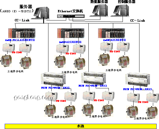
Figure 1: Schematic diagram of the simulation platform
2.2.1 AnSH PLC features and configuration
A1SJHCPU is the most economical CPU component of the AnSH series. The unique feature of the A1SJHCPU is its CPU, power supply and substrate set as a whole, which significantly reduces the cost of manufacturing. AnSH uses Mitsubishi’s “Mitsubishi Sequential Processor Chip” (MSP) for sequential control and mathematical operations. AnSH is not only faster than AnS, but also increased the CC-Link special instructions, the original instruction is still retained (including PID operation, floating-point operations and trigonometric functions, etc.). At the same time built-in performance such as lithium batteries, backup RAM, user memory, real-time clock and a flexible communication port, so that the AnS series can adapt to a wide range of applications. The completeness of its special functional components makes the AnSH perfect for process control, position control and various other types of controls. Compared with similar products, the price is relatively high, which is our reason to choose AnSH. among them:

Figure 2: AnSH
Figure 2: AnSH PLC configuration
1) A1SH42 digital input / output module: the main control of some control relays, contactor opening and closing state, and the relay with the control motor and inverter power supply on and off state.
2) A1SJ61BT11 CC-Link field bus communication adapter: mainly used for communication with the CC-Link master module in the system server. Real-time transmission AnSH PLC monitors the status and parameters of each quantity, and receives the control commands from the server.
3) A1S66ADA analog input / output module: real-time monitoring of the pool of water pressure trends (the level of response to the sea), to the FR-E540 inverter to provide analog control, the inverter output frequency changes, to control the three-phase asynchronous motor The purpose of speed, so as to control, simulate the sea waves and waves, waves Cheng.
4) A1SD62D high-speed counting module: real-time monitoring of three-phase asynchronous motor speed, so that A1S66ADA module on the motor speed PID regulation.
2.2.2 FX2N PLC features and configuration
FX2N series is the most advanced series of PLC FX family, it is the most extensive range of standard features, the program execution faster, fully complement the communication function, suitable for different countries around the world and meet a single need for a large number of special function modules, Factory automation applications provide maximum flexibility and control. Because FX2N PLC has a good price, it not only has a better hardware configuration performance and functional performance, there are a wealth of software function instruction set, is a small representative of the small PLC, and it has no speed to match, Advanced features, logic options and positioning control and other characteristics, FX2N from 16 to 256 input / output of a variety of applications options. Its flexible configuration, high-speed computing, outstanding register capacity, rich component resources, especially for small points of process control. among them:

Figure 3: FX2N
Figure 3: FX2N PLC configuration
1) FX2N-64MT-D master module: its digital input / output module control some control relay, contactor opening and closing state, and the relay with the control motor and inverter power supply on and off state.
2) FX2N -32CCL CC-Link field bus communication adapter: mainly used for communication with the CC-Link master module in the system server, real-time transmission FX2N-64MT monitor the status and parameters of each quantity, and receive the control command from the server The
3) FX2N -4AD analog input module: real-time monitoring of the pool of water pressure trends (the level of response to the sea);
4) FX2N -2DA analog output module: to the FR-E540 inverter to provide analog control, the inverter output frequency changes, to control the purpose of three-phase asynchronous motor speed, so as to control, simulate the sea storms and waves, waves Process
5) FX2N-HC high-speed counting module: real-time monitoring of three-phase asynchronous motor speed, so FX2N -2DA module on the motor speed PID regulation.
2.2.3 server configuration
CC-Link is master-slave mode. Therefore, a master mode CC-Link communication adapter card must be inserted into the master server in the central control room: A80BD-J61BT11. In order to improve the real-time control of its control, the communication rate is 2.50, and the operating system uses Windows NT4.0 + SP4. The programming environment of the system is Visual C ++ Ver6.0. And installed SQL Server V7.0, for human-computer interaction, CC-Link network configuration, real-time database access, historical data playback, control command delivery and decentralization tasks, simulation of three-dimensional graphics display.
2.3 CC-Link field bus
CC-Link is a short form of Control & Communication Link (Control and Communication Link System), which is an open field bus, a device layer-based network with large data capacity and multi-level communication speed, and it is a composite , An open, adaptable network system that can adapt to a higher management network to a lower range of sensor layer networks. Can be achieved from the CC-Link to the AS-I bus connection. CC-Link has a high-speed data transfer speed, up to 10Mbps. CC-Link’s underlying communication protocol conforms to RS-485. In general, CC-Link mainly communicates by means of broadcast polling. CC-Link also supports instant communication between master station and local station and intelligent device station.
CC-Link. With outstanding performance, the widespread use of simple cost savings and other outstanding advantages.
2.4 System reliability design
PLC output module within the small relay contacts are small, broken arc capability is poor, can not be directly used for plant ~ 220V ~ 380V circuit, you must use PLC to drive external relays, with external relay contacts drive ~ 380v load The At the same time more AC220V ~ 380V solenoid valve with its coil in series with the limit switch normally closed contact, solenoid valve coil power, spool action, is the internal contact with the valve to disconnect the circuit. In this case, to use a smaller contact relay to transfer the PLC’s output signal. The system uses a high-power thyristor device, PLC should stay away from strong interference sources. PLC can not be installed with the high voltage electrical appliances in the same switch cabinet, PLC should be away from the power line in the cabinet (the distance between the two should be greater than 200mm). And PLC installed in the same switchgear inductive components, such as relays, contactor coil, should be parallel RC arc suppression circuit. PLC I / O lines and high-power lines should be separated from the line, such as must be in the same trunking wiring, signal lines should use shielded cable.

